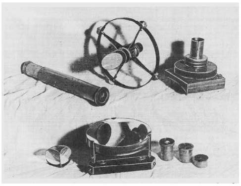
The Light Source
Reasonably monochromatic light is required for testing selected pieces of plate glass as well as the figured diagonal. This light may be obtained from any of the now rather common gas-tube lights; an inexpensive neon lamp is excellent, and argon is also good, but requires a darkened room. Either type may be purchased at a radio supply store. The bulb may be screwed into an ordinary light socket; an adjustable desk lamp is convenient. A thin piece of absorbent tissue wrapped around the bulb will provide satisfactory diffusion. The specimens to be tested should rest on a piece of black cloth almost directly below the light. With these small specimens, the interference bands should be spread out, by pressing, until they are about 1/4″ apart.
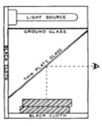
For precision testing of large flats (see Appendix B), the sharper bands to be had from the sodium, helium, or mercury-vapor lamps are much to be preferred. (Information on these lamps can be had from George W. Gates & Co., Inc., Franklin Square, N. Y.) A filter excluding all but the green line should be used with the mercury lamp. With any of these lights a diffusing medium, such as tracing cloth, opal or ground glass, must be used. For accuracy, both light source and eye should be placed as near as possible to the normal to the surfaces under test. An arrangement that places both eye and illuminant normal to their centers is shown in Fig. 51. Gross error may result from oblique viewing.
Testing for Flatness
Plane surfaces are tested for flatness by placing two polished surfaces together and observing the interference bands that appear between them when viewed under monochromatic light. The surfaces must be clean and free of all grease and dust or the bands may not show up.
Because of its wave nature, light reflected from the surfaces under test alternately reinforces and interferes with itself, interference occurring with each successive half wave length of separation of the surfaces, which points are marked by the presence of dark bands, or fringes. These bands can be interpreted just as are the contour lines on a topographic map, where the terrain along any given line is all of the same elevation. For example, the surfaces in Fig. 52 are, anywhere along band 2, a half wave length farther apart than they are along band 1; anywhere along band 3 they are a half wave farther apart than along band 2, and so on.
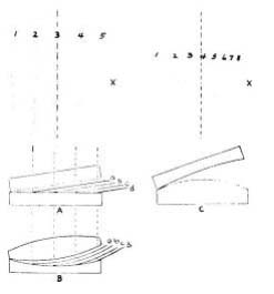
Flat surfaces, A in the diagram, or spherical surfaces of equal radii, B, present identical band patterns. The direction of greatest separation, or the direction of the wedge opening, can be found by pressing at one side or the other. Pressing at the left tilts the top piece at a steeper angle, widening the wedge opening, and as more bands move in they become thinner and more closely spaced. Pressing at the right, at x, narrows the wedge opening; as the bands move out they become broader and fewer in number until only one band, spread out across the whole specimen, may be seen when the surfaces have been brought parallel to each other.
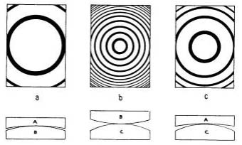
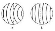
Where one or both surfaces are not flat, curved bands may be seen, resembling the appearance in Fig. 52C. A little reasoning will show that, by placing a straightedge along the bands, as indicated by the dotted line, and counting their number intersected by it, the amount of convexity (or concavity) can be determined. At C, three bands are cut through, hence the surfaces are either convex or concave to each other by l½ wave lengths. The changing band appearance under appropriate pressure will disclose which is the case. By pressing at the right, at x, narrowing the wedge opening, the bands (in this case) will move off in that direction, and the bull’s-eye, or center of the fringe system, will come into view, having the appearance of Fig. 53c (where the same specimens are again tested). The departure from flatness can then be determined by counting the number of rings visible; in this case three rings are present, hence the surfaces are 1½ waves off.
Note that the bull’s-eye, in the case of convexity at the point of contact, moves toward the point of pressure. Or, if convexity is so slight that the bull’s-eye is not in evidence, the curved bands, convex toward the wedge opening, move, convex, toward that point when pressure is applied there. In the case of concavity, the bull’s-eye would mark the point of widest separation of the surfaces, and in that case, application of pressure at the center would cause the rings to flow inward and to become fewer in number; the bull’s-eye would recede from a point of pressure at any edge. With only curved bands showing, as in Fig. 52C, the wedge opening, with concavity, would be at the left; by applying pressure there to narrow the wedge, the bands, concave toward that point, would move in that direction and become fewer in number. By these means, the relationship of the contacting surfaces to one another is easily determined.
In commercial optics, surfaces are tested against a master flat of known precision, so the exact condition of a specimen is immediately known. Although you may have no master flat, you require only three specimens of good plate glass and a little elementary algebra to measure with equal accuracy the flatness of a surface of each specimen. A hypothetical problem is illustrated in Fig. 53, for three pieces of glass marked A, B, and C.
Placing A on B, we get the pattern of bands shown at a, one band convex. B on C gives the pattern at b, eight bands convex. A on C results in the pattern at c, three bands convex. (When making an actual test, several minutes should be allowed to elapse before writing down each result, as heat from the hands will introduce temporary errors.) Convexity is usually assumed to be positive (plus), and concavity negative (minus), so the following simultaneous equations may be written:
A + B = + l; B + C = + 8; A + C = + 3.
Solve the first equation for B and substitute the result, 1~A, in the second equation. This gives two equations:
A – C = – 7, and A + C = + 3.
Solve the first equation above for A and substitute the result, C — 7, in the last equation, whence 2C = +10.
From this solution, C = + 5, B ~ +3, and A = — 2. Remembering that from one band to the next represents a difference in surface separation of ½ wave length, then
A = — 2 bands, or 1 wave concave,
B = + 3 bands, or 1½ waves convex,
C = + 5 bands, or 2½ waves convex.
Making the Diagonal
By the testing procedure just described, we find the exact condition of the surfaces of three pieces of plate glass. Let us keep the best (A in the above case) for testing, and undertake to correct one of the others, say piece C. Other pieces of the same thickness should be cut up so that they can be fitted on the flat side of the glass tool on which the mirror was ground, as in Fig. 54. Or, if the preferably smaller sized diagonal, 1 3/16″ x 1 5/8″ (2″ long if it is to be made elliptical), is going to be used, four or five pieces of this size can be grouped at the center and surrounded with “filler”‘ pieces. By this arrangement, upon completion of the work, you will have the choice of the best of several pieces.
As will be seen from Fig. 59, to avoid needless obstruction of light, one edge of the diagonal should be ground off at a 45° angle. This is done by holding the diagonal between thumb and fingers, at a 45° angle to the piece of scrap glass on which the grinding is to be done. The bulk of glass can be removed with No. 80 carbo, terminating with No. 220. The other edges can be ground squarely and neatly, also with No. 220, and a very small bevel ground on each corner with No. 400. This last operation may best be deferred until polishing and figuring are complete, but then great care must be taken to keep the fingers from contact with the polished surface, or scratches are almost sure to develop. If the arrangement of making several diagonals in the same block is followed, then the grinding of the edges will have to be postponed until final selection of the piece for the diagonal is made. If the diagonal is to be made elliptical, the operation described in this paragraph is replaced by that outlined later in this chapter under the section on An Elliptical Flat.
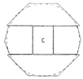
The back of the tool on which the mirror was ground often consists of waves and ripples; this also applies to any piece of plate glass, and unless it is first corrected it will not make a satisfactory foundation on which to cement the diagonal or diagonals. In fact, both surfaces must be made to match each other quite exactly, and it is with this aim that we now proceed. The second 6″ disk mentioned among the additional materials needed fof the diagonal will be required for the diagonal polishing lap, so by grinding one surface of it and the back of the mirror tool together with No. 400 carbo, the back of the tool can be reasonably well corrected. In order that the tool will not rock on its convex surface when inverted, it should be balanced in a large hole 4½‘ in diameter, cut in a thick piece of cardboard.
For this grinding, two charges of carbo should be used, with a one-quarter diameter stroke, alternating the positions of the disks frequently in order to preserve, as nearly as possible, uniform flatness. Next, the several pieces of glass that are to be mounted on the tool (see Fig. 54) should be separately ground, very briefly, against its flat surface with No. 400 carbo. This will bring the surfaces into close harmony, the intention being to eliminate any danger of warping or deformation resulting from the cementing together of ill-fitting surfaces.
Now lay the tool on a board and place it in an open oven, or near a source of radiant heat. Heat slowly and uniformly until the glass is hot enough to melt the paraffin (about 150° F.). The diagonal and the other pieces should also be heated, but not to a degree that they cannot be handled. Remove the tool from the oven, and wipe its flat surface with a stick of paraffin (or brush on melted paraffin), leaving it coated with just a very thin film. Lay the diagonal, ground side down, in the center, and squeeze it down firmly and evenly. Then place each of the other pieces in position, pressing them down also, so that only a very thin film of paraffin binds them. A space of about 1/16″ should be left between edges. If, when the assembly is ready for polishing, any abrasive grains lie at the bottom of these spaces and cannot be dislodged, a few drops of shellac will seal them in. Some workers prefer to fill in this space with paraffin or beeswax, but in doing so there is danger of disturbing the seating of the diagonal. If a filler is used, it should then be recessed with the point of a knife, so that it cannot collect abrasive which may later become dislodged and cause scratches. The grooves should be thoroughly scrubbed out when changing grades, and the filler further recessed before polishing.
The over-all surface of the cemented pieces will hardly be found to be in the same plane, but the differences can be corrected by grinding, when cool, against the back or yet unused surface of the second disk. Use No. 400 carbo, a short stroke, and invert positions for each charge in order to forestall the natural tendency toward curvature. By doing the leveling off on the back surface of the second disk, we avoid “grooving” the surface already made nominally flat in the initial operation. To avoid confusion in identity, the first surface should be marked in some way.
Now, the combination “flat” (diagonal and supporting pieces) and the flat surface of the second disk must be ground together with one-quarter strokes, first with No. 600 alundum, and then with No. 305 emery, after which you are ready for polishing. The positions of the disks should be inverted for each successive charge, using eight charges of No. 600, and six of No. 305. When the fine grinding has been completed, both surfaces should test perfectly flat with a good straightedge laid across any diameter.
The Lap
The paraffin-cemented combination cannot be made use of in making the lap, as obviously no heat must be allowed to penetrate it. A channeled lap can be made on the second disk, but a sufficiently large piece of plate glass will have to be used for the preliminary shaping of the surface. For a molded lap, proceed according to the instructions in Chapter 5, making it on the piece of scrap plate glass, which in this case must be substituted for the “mirror,” that is, for the combination flat. For flat work, the facets of the molded lap should be uniformly spaced throughout, so another rubber mat will have to be made. If it is thought too much work to make separate mats for mirror and flat, then one of regularly spaced holes, having a 1/16″ tangential separation, should be made to serve for both operations. This will work about as well on the primary mirror as the one with graduated spacing, and it has the advantage of symmetry.
After coating the lap with beeswax, soften it in hot water for a few minutes. The scrap piece of plate glass is once more called into use. Paint it with a thick mixture of the polishing compound, and when the lap is removed from the hot water, work the plate glass vigorously on it, pressing down the uneven wax coating, and charging it well with the polishing agent. Again soften the lap in hot water; then press into contact with the combination flat, first spreading a piece of onion sacking over the lap. Let stand for about 15 minutes, using about 10 to 15 pounds weight in pressing; use the board that was employed in mirror pressing.
Polishing and Testing
For the polishing agent, either cerium oxide or Barnesite is preferred to rouge. After about 15 minutes of polishing, using a one-quarter diameter stroke, a test should be made to determine the benefits of the grinding. The test, of course, should not be made immediately, but after a 15-minute wait. If the diagonal proves to be more than a wave length convex or concave (indicated in the first instance, when tested with hypothetical piece A, by straight bands, or curvature due to convexity, and in the second instance, by four or more bands concave), then the difference is best corrected by further grinding.
It is most probable, however, that any error will be within •the above tolerances, and polishing can be resumed, the nature of the surface determining the method. If convex, a one-third or longer stroke can be used, in the normal positions; if concave, polishing should be done with the lap on top. The condition of the surrounding pieces does not matter, their purpose being to extend the working surface to such a size that it will not wobble or rock under the motions of grinding and polishing. On account of the broken-up surface, the onion sacking should be used at all limes in pressing. When the diagonal has been completely polished, half an hour should elapse for temperature adjustment before testing.
Try to figure the diagonal as closely as possible to absolute flatness, indicated by testing two bands concave with piece A. If an optical flat is available (see Appendix B), curvature of 1/10 of a band is easily measured with straightedge and dividers, as shown above in Fig. 55. Against an optical flat, of course, an appearance like that in Fig. 52, left, indicates absolute flatness.
To free the finished diagonal, place the disk in a pan of very hot water, or lay it on a board and heat it slowly in an open oven. Any wax still adhering to the diagonal can be wiped off with a cloth dipped in turpentine.
If several diagonals have been made in the same block, as previously suggested, it may be desirable to test them one against the other; therefore, in order that the interference bands may be visible, their ground backs should be given a semipolish. This can be quickly done by charging the surface of the lap with No. 600 alundum, and scrubbing the back of each piece 011 it for a few minutes. Or, if it is desired not to destroy the lap, grind the backs of the separate pieces on a scrap piece of glass briefly with No. 600, followed by a brief polishing on the lap.
The diagonal can now have the final bevel ground on its corners, if the 45° edging has already been done. If the edging has not been done, be careful in the procedure to avoid scratching the polished surface. This operation need not be performed, however, if the diagonal is to be made elliptical.
An Elliptical Flat
With a not excessive amount of labor, a rectangular diagonal can be converted into one of elliptical shape. A simple diagram will show that the length of the rectangular diagonal as prescribed by formula will have to be increased by the thickness of the plate glass used. Therefore, the 1 3/16″ x 1⅝” diagonal made of ⅜” glass should be made from a rectangular piece 2″ long, as already mentioned.
A stick of hardwood about a foot in length should be turned up to a diameter equal to the minor axis of the diagonal, and given two or three coats of shellac. One end is cut off at a 45° angle, and the figured surface of the diagonal cemented to it with hard pitch, thus giving it protection in the grinding to follow. In order to make a good bond, both the end of the stick and the diagonal should be preheated before applying the hot pitch.
The corners are ground all around on the scrap piece of plate, using No. 80 for the bulk of the work, and finishing with No. 120. Hold the stick horizontally, and work all over the plate, rotating the stick the while. Five to 10 pounds of pressure can be applied at the diagonal end of the stick. One to two hours will suffice.
To free the diagonal, insert the edge of a razor blade into the pitch binder and strike it a light blow; any pitch adhering to the glass can be dissolved in turpentine. The result is a neat-looking elliptical diagonal, offering a minimum of obstruction to the light. With thick glass, it is most unlikely that its figure will be in any way impaired through removal of the corners.
The above grinding can be done in a lathe as well, holding the stick in the chuck, running at slow speed, and using a sheet of brass or band iron held against the edges of the rotating diagonal, with carbo and kerosene or water fed into it. Particular care must be exercised to protect bearings and ways from abrasive.
There is another way of making the elliptical diagonal, available to the possessor of a drill press. A 6″ glass disk, about %” thick, and a second one of equal diameter, but at least ¾” thick, are required; the tool on which the mirror was ground will also be used. The surfaces of the ⅜” thick disk, and the one to which it is to be cemented after perforation, will no doubt be at considerable variance with each other, so they should be first ground together, using two charges of No. 400 carbo, working the second one down well. During this operation, the positions of the disks should be alternated several times. This will bring the two surfaces quite flat and into close harmony.
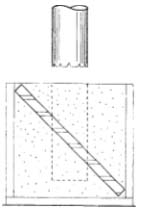
Stand the ⅜” thick disk on edge diagonally (45° angle) inside a rectangular box 4¾” or 5″ to the side, and completely surround it with plaster of Paris, filling the box. When it is thoroughly dried out, which may take several days, tack a cover on the exposed side, and remove one of the adjacent sides. With a suitable length of thin-walled brass or copper tubing of correct inside diameter, mounted and held in the drill-press chuck, running at slow speed, and using No. 120 carbo and kerosene or turpentine, bore through the plaster and glass (Fig. 56). Boring will proceed more rapidly if several V-shaped nicks are made in the edge of the tube with a three-cornered file. When the boring is completed, the box can be opened up and the plaster broken loose.
After perforation, the surface fit between the tool and the diagonal with its surrounding glass disk will have been upset by the relieving of strains in the glass. The surfaces should accordingly again be ground together, separately of course, but this time with No. 600, as the differences will be slight. The perforated disk and elliptical diagonal are now cemented with paraffin to the flat back of the “mirror-tool,” in the manner previously described. For surfacing, fine grinding and so on, proceed by methods already described.
