A Portable Mounting
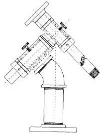
Table I lists sizes and descriptions of parts for both permanent and portable mounts. A 45° elbow with a tee, used as shown in Fig. 71, rather than the wye of Fig. 72, is preferred for the portable mount, as it dispenses with the counterweight on the polar axis. The wye is more rigid, of course, and so is chosen for the fixed mounting. In thus dispensing with the counter-weight, the radial thrust load on the polar bearing is in-creased and is in counter directions at the opposite ends. It may therefore be desirable to increase this bearing area by using the parts listed under “B” in the table. This is strongly recommended if an additional five or six pounds can be tolerated.
The gain is not only in an increased diameter of the polar-axis bearing, but also an increase in the length of both bearings, as a comparison of the proportions of the respective tees will show. The additional length in the bearings is an important factor in gaining added rigidity. The mounting, detailed in Fig. 73, and weighing but 17 pounds, is the one shown in Plate VI (page 126). As the difference in cost is little, brass fittings are to be preferred. Brass is easier to machine than iron, will not rust, and has a more pleasing appearance. Also, the inside surfaces of the brass fittings can be tinned, thereby providing a secure anchor for the babbitt. The standard brass flange is not sufficiently heavy to support the saddle and tube adequately,
but there is a similar fitting known as a flange union, consisting of two heavy flanges (3½” in diameter in the 1″ pipe size) which comes as a unit, and it may be possible to pick up an odd one. Machining steps will be described following the discussion of the tripod.
|
|
The Tripod
The combination of tripod and pillar (frontis-piece) was devised in order that the telescope could be swung through the meridian without fouling the legs. The only other way in which this could be accomplished would be to extend the declination axis several inches beyond its bearing support, thereby increasing the bending moment.
No weakness was introduced by the pillar, which proved to be exceedingly rigid. In construction, it consists of a 9″ length of aluminum tubing, 4½// outside diameter, with a 1/8″ wall. Tightly fitting caps at each end were built up of three thicknesses of 5/8″ plywood, glued together, then turned in the lathe and perforated to admit the pipe that is screwed to the mounting. This pipe passes all the way through the pillar and is made up tight at the bottom by means of a lock nut. The three 2″ blocks of maple to which the legs are attached were first glued to the lower cap, and included in the turning and boring operation.
For the f/8 telescope, the pillar construction may prove every bit as rigid if it consists simply of, a 10″ length of pipe, extending from the 45° elbow, and a heavy flange screwed onto its lower end. The flange in turn can be bolted to the wooden tripod head, or the pipe can be screwed directly into the tripod head of metal shown in Fig. 76. If this form of construction is adopted, the tee that houses the polar axis should then be of the “bullhead” type shown in Fig. 73, with a 2″ branch opening.
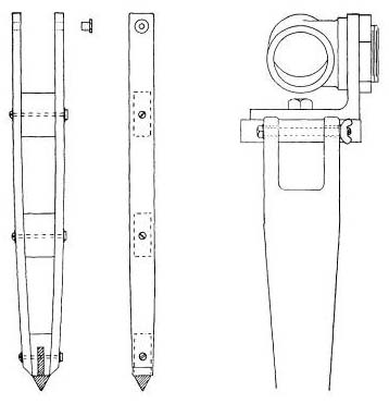
The legs of the tripod are made of maple, although any hard-wood will do. The slats are 0.4″ thick, l½” wide, and 21″ long. The oak spacers are l 1/8″ thick, the upper ones being the same width as the head blocks (2″), and the lower two tapered, narrowing down to 7/8″ at the bottom. The pegs or feet are made from 1″ bar stock, 31/4″ long. One half of this length is reduced to a neck with a diameter of 3/8″; the other half is tapered to a point. The neck is pushed into a 3/8″ hole drilled into the lower wooden spacer. When glued and bolted together, the leg assembly (Fig. 74) makes an extremely rigid truss member. A synthetic resin glue, such as weldwood or cascamite, mixed to a thick creamy consistency, is recommended. The overall height is 31″ from the floor to the top of the pillar with the legs spread at an angle of 60° to the floor.
|
|
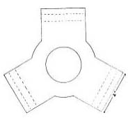
The legs can also be fashioned from a solid board, as suggested in Fig. 75, but the board should be not less than l1/4” thick and 3″ wide. As in the design in Fig. 74, brass bushings should be inserted into the holes to take up the wear against the joining bolts. See page 180 on how to tie tripod legs together. A wooden pattern for the tripod head, similar to Fig. 76, is easily made, and a casting in iron, brass, or aluminum made up at a local foundry. The diameter is a matter of choice, the larger the better, but 5½” is about the limit if the tube is not to tangle with the legs. A good thickness is about l½“. Make the center hole about 1¾” in diameter, and very slightly taper it and all the sides of the pattern in the same direction, so that the foundryman can remove it from the sand. To accommodate the 2″ pipe, the center hole should later be bored out to a diameter of 2.236″, and then threaded squarely with a 2″ pipe tap, sufficient threading being cut to admit all but about the last thread on the pipe when it is made up tight. The only other machine work required on the casting is the drilling of the three holes (5/16″ or 3/8″) for attaching the legs. The sides there should, of course, be filed until they are quite parallel.
|
|
Machining the Parts
The following suggestions of step-by-step operations for making a machined mounting similar to the one shown in the frontispiece might be thought to be useful only to those having access to machine-shop facilities. It has been suggested, however, that an amateur not equipped to do the work himself might farm it out to a local machine shop. The idea is a practical one, and while it is difficult to assay the cost of such a project, the figure is not likely to be much in excess of 20 dollars. After learning what is needed, the machinist can then either follow the steps outlined here or substitute other and better methods for achieving the desired results.
The parts used in this description are the same as those used in the mounting in the frontispiece and listed under “A” in Table I, but, as previously mentioned, substitution of the parts listed under “B” can be made if desired. On account of the small difference in diameter of pipe and fittings, the internal threads of the tees must be bored out to create sufficient space for the babbitt.
The external and internal threading on pipe and fittings is tapered, so that a tight joint can always be made up, but in so doing several threads always remain exposed. Furthermore, the pipe is never perfectly round, and may have scorings on it from the fitter’s wrench or vise jaws. None of this annoys the steam-fitter, but the telescope maker is going to utilize short lengths of this pipe (or long nipples, as they are called) for his polar and declination axes. To turn in bearings, these must have shafts that are truly round and smooth right up to the shoulders of the fittings to which they are joined.
The declination nipple screws into a heavy flange and the polar nipple into a tee, so the internal threads of both these fittings must be tapped deeper with a 1″ pipe tap, to permit further entrance of the pipe threads. This should be done a little at a time, and the nipple tried frequently, until when made up tight with a wrench only one or 1½ threads remain exposed.
In using the wrench, apply it near the opposite end of the nipple or, better, to a spare fitting such as a coupling which has been temporarily screwed on there. This will avoid scoring or bending that part of the pipe to be encased in the bearing. Two pipe wrenches are convenient for working one against the other. Once the pipe has been rounded in the lathe, the wrench should never be applied directly to any part of it, for fear of deformation. Screw a spare coupling on the free end and apply the wrench to that.
When turning the nipples in the lathe, remove only a minimum amount of metal in order not to thin the walls any more than is absolutely necessary. Removal from the newly poured bearings will be made easy if, at the same time, the nipples are given a taper of about 0.001″ for each inch of their length. Therefore, for those two operations, the tailstock center should be offset about 0.008″.
1. Make up the declination axis nipple in the heavy flange. Hold it in the chuck, running true, and cut off any excess length that protrudes beyond the back face, recessing it to about 1/32″ below the face of the flange. At the same time bore out the inside of the nipple to a depth of about 1/4″, removing a minimum of metal.
|
|
2. Turn up from scrap stock a metal plug to fit into the above bored-out end. Return the first assembly to the chuck and center-drill into the plug for the tailstock center.
3. Make up the polar-axis nipple in the reducing tee. The end will be seen to project inside where it will be in the way of the babbitt, so after noting the length of the excess projection, remove the nipple and cut this excess off, after which the nipple is returned to the tee. Hold the nipple in the chuck, running true, and center-drill into the back of the tee for the tailstock center.
4. The tailstock center is now offset about 0.008″ away from the worker; the diameter of the work will thus be tapered in the direction of the chuck end, where it should be least.
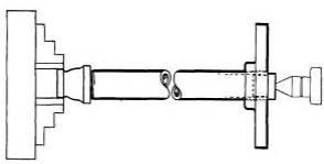
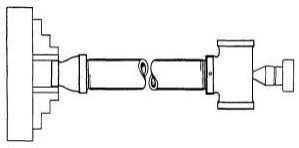
5. A spare coupling is screwed firmly onto the end of the declination assembly, and held in the independent chuck with the tailstock center supporting it at the other end (Fig. 77). Adjust the chuck to run true. Machine all parts indicated by the heavy lines in the diagram except the back face of the flange, which would be made conical instead of flat if done while the tailstock center is offset. To face this surface, remove the coupling and hold the machined nipple in the chuck, running true. This will bring it reasonably square with the axis of the shaft. Reverse the assembly, holding the flange in the chuck, and turn off the tops of those threads on the other end of the nipple that had been covered by the coupling.
|
|
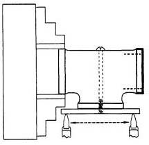
6. Screw the spare coupling on the free end of the polar-axis nipple, and hold it in the independent chuck, running true, with the tailstock center supporting the tee end (Fig. 78). Machine the surfaces indicated by the heavy lines. For further machining, it is necessary to remove the nipple from the tee, but first, to insure later return of the parts to the same exact positions, a small hole into which a pin or screw can later be inserted should be drilled through the two parts, as is indicated in the diagram. (A No. 44 drill, tap size for a 4-36 screw, will do.) After removing the coupling and unscrewing the nipple, reverse the assembly in the chuck and turn off the tops of the threads at the other end.
7. The faces of the reducing tee must now be machined, parallel to each other, and at right angles to the branch face. The small center hole in the back of the tee is enlarged to allow entry of a long screw which threads into a 3″ length of flat bar stock, which is then drawn firmly against the machined branch opening of the tee. Hold the tee in the chuck (Fig. 79) and adjust until a tool point just contacts the surface of the flat bar evenly, along its length, as the lathe carriage is moved along the ways. Thus insuring that the face of the flange will now be made quite square with the branch opening, remove the bar. The face and outer shoulder of the tee can now be machined, and the internal threads at that end bored out. Reverse the tee in the chuck and repeat the operations at the other face, making both outside diameters equal. The faces should be parallel to each other within about 0.001″.
8. Only one face of the second tee need be machined, but as it may be desired to put a collar on the lower end of the polar axis, it is best if both faces are machined parallel to each other. The internal threads must, of course, be bored out. This tee should first be experimentally made as tight as possible with close nipple and elbow, and the face that will be uppermost marked for identification, for example, by spot drill-into the shoulder with a small drill, or by filing a notch in the edge.
|
|
9. The backs of both tees are now drilled and tapped for the clamping screws L, Fig. 72. Tinning the inside of the tees to pro- vide more secure anchorage for the babbitt is optional.
10. Four collars, preferably of aluminum because of its light weight, must be turned up either from solid stock or from castings, and bored out to suitable diameters to provide a neat fit on the shafting. Make the faces. of these collars parallel and square with the boring. The outside diameters should be concentric with the borings, and of the same diameter as the shoulders of the tees. This will facilitate easy centering of the shafting when you are getting ready to babbitt. The width of the collar at the upper end of the polar axis should be such as to bring the intersection of the axes vertically over the center of the tripod (see Fig. 73). The collar at the upper end of the declination axis ought to be at least 1″ wide. The width of the other collars is optional, and they should be provided with two set screws each, spaced 120° apart.
11. Three holes, 120° apart, near each end of both tees, should be drilled and tapped for No. 6-32 screws (Fig. 80) which support the pipe or shafting centrally for the babbitting operation. Also drill two small holes near each end of both tees, to allow the escape of air. The ends of the centering screws should be filed smooth to prevent their scoring the pipe. The ends of the 3/8″ clamping screws (L, Fig. 72), which can be made or purchased, are filed or faced off flat.
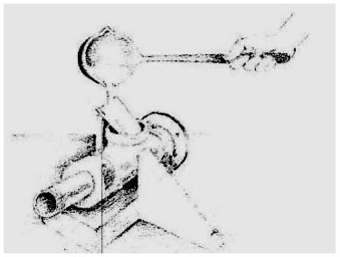
 12. The details of the babbitting operation have already been described in the making of the fixed mounting. About half the quantity of babbitt that was required there is needed for the portable mounting. The declination bearing is the first to be poured, and is assembled as shown in Fig. 81, after first coating the pipe with oil and lampblack. Be sure to insert the clamping screw. Be careful not to fill too much with the babbitt. After cooling, remove the centering and clamping screws, screw a coupling onto the end of the nipple and drive it out with a few light blows of a hammer. That end of the tee adjacent to the flange should first be marked to identify it as the large end of the bearing. |
|
|
|
Now screw the polar axis back into this tee until the previously drilled hole (operation 6) is in alignment; there a pin or screw should now be inserted. Coat the nipple with oil and lampblack and make up the assembly as in Fig. 82, ready for babbitting. The previously marked face (operation 8) of the tee which is to house the polar bearing must be placed adjacent to the collar that fits against the screw joint, and while it is held centered the centering screws are brought up to just touch the polar axis, enough to keep the assemblage from shifting. The two bearings will thus be brought at right angles to each other with all reasonable accuracy. The second collar is brought up flush against the face of the tee, and held there by means of its own set screws. In preheating this assembly, keep the torch flame away from direct contact with the babbitt of the declination bearing.
When the mounting is finally assembled, two wafers of leather, vellumoid, or some friction material are cut out and inserted before the clamping screw of each axis; these cushion the thrust of the screws and prevent their scoring the shafting. After the pipe nipples which constitute the declination and polar axes have been trued up in the lathe, under no circumstances should they be held in a vise, on account of the almost certain probability of their becoming deformed. Screw a fitting on the exposed threaded end, and apply the force to that. Use two pipe wrenches, cautiously, in removing the tightened fitting.
